


EV Charging Stations
Filtration for Power Equipment
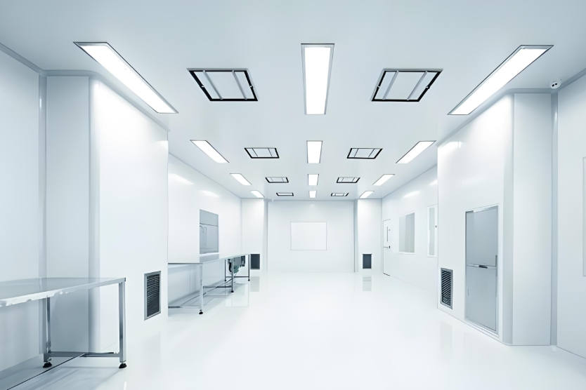
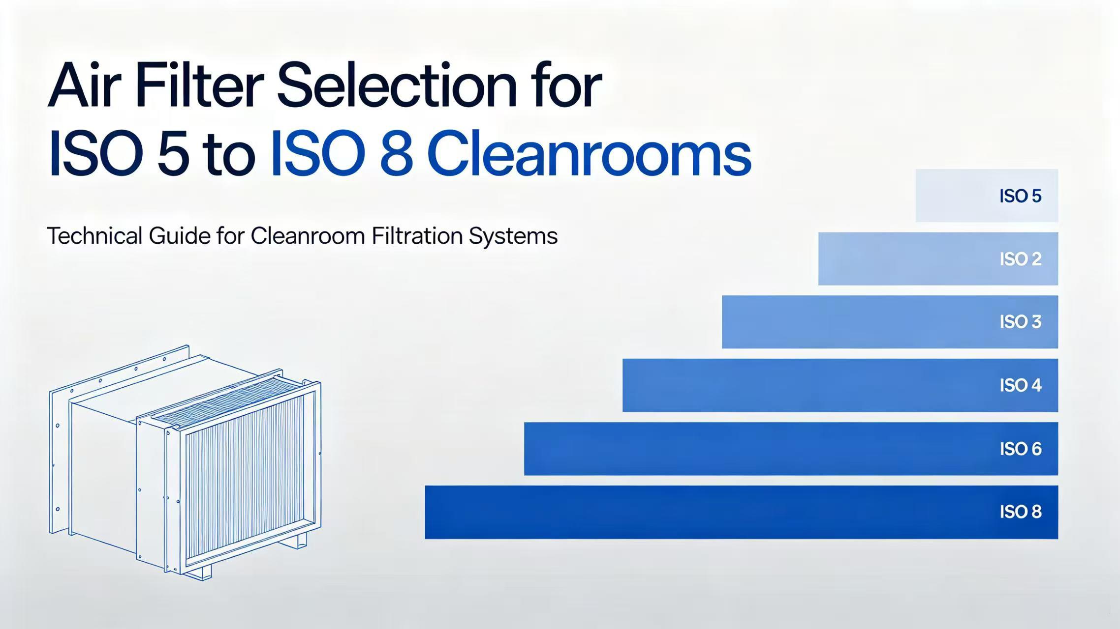
Cleanroom & Semiconductor
Ultra-High Cleanliness Filtration
Commercial HVAC
Central Air System Filtration
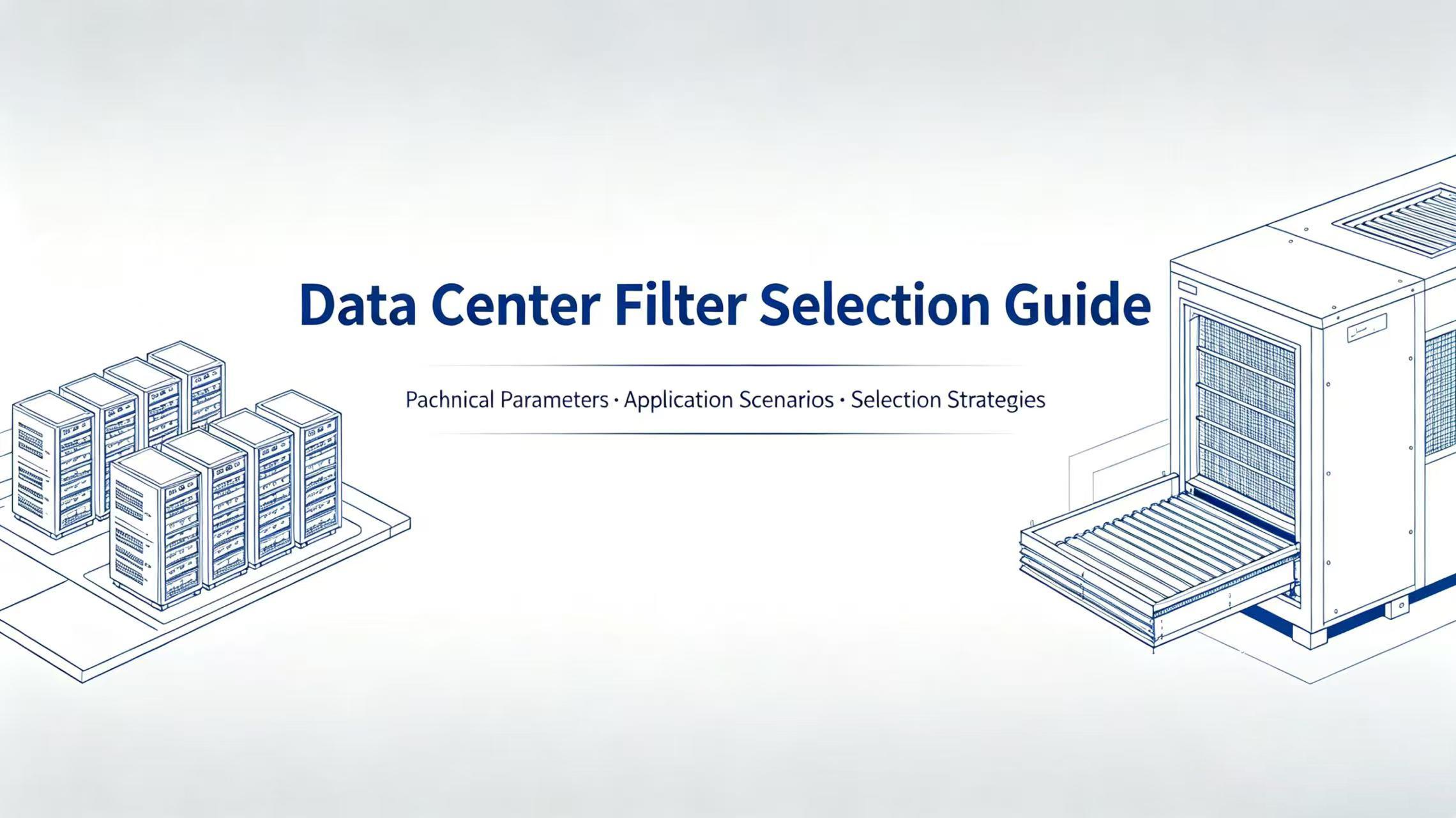
Data Centers
Precision Equipment Protection
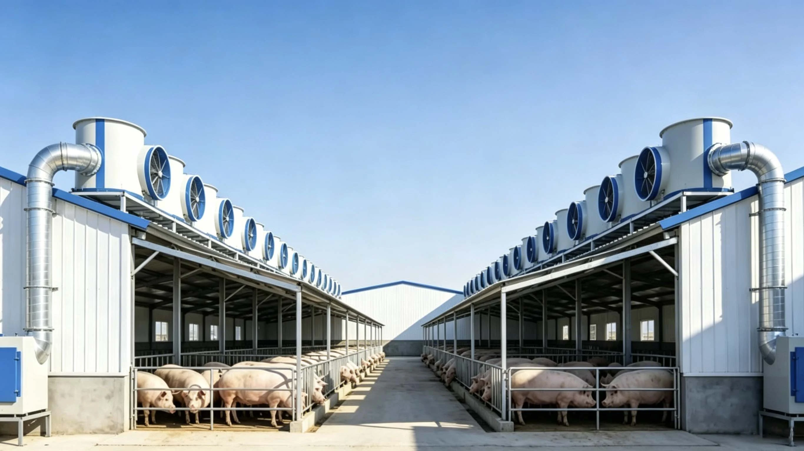
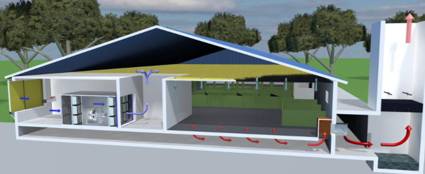
Livestock & Farming
Farming Environment Purification
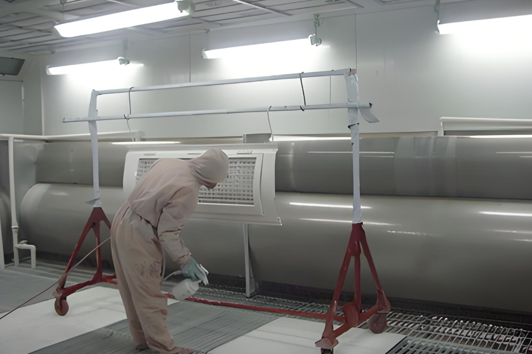
Spray Booths & Industrial Dust
Paint Mist & Dust Purification
Filtration for Power Equipment
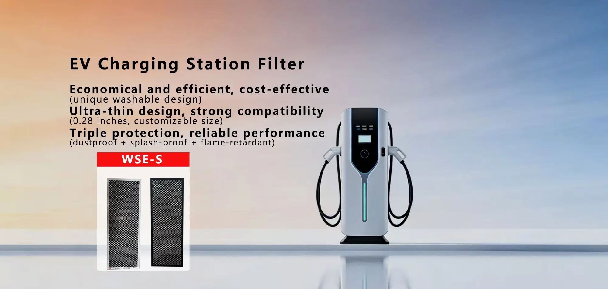
Professional air filtration for EV charging devices, protecting against dust and sand ingress to ensure stable, reliable operation of charging piles and station infrastructure.
View Related Products →Ultra-High Cleanliness Filtration
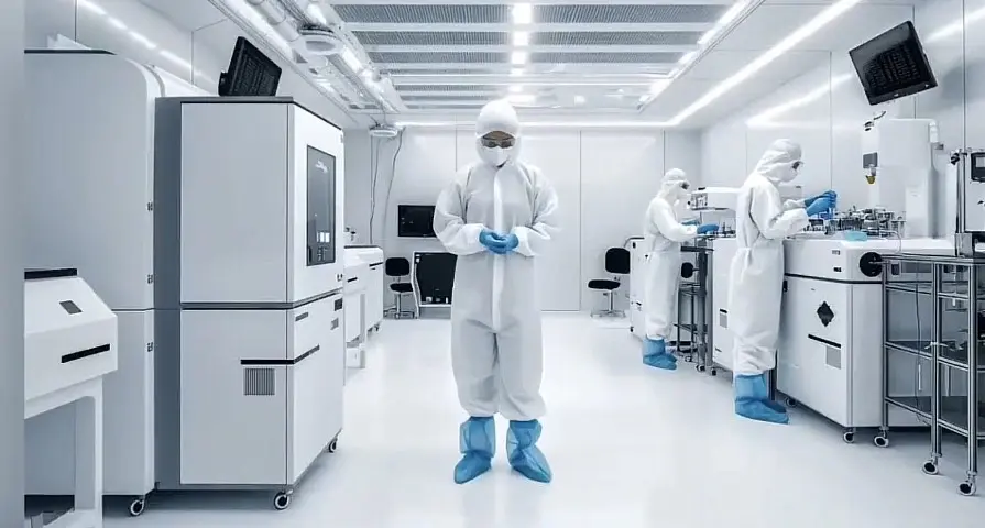
Ultra-high efficiency filtration for semiconductor wafer fabs and precision electronics cleanrooms, capturing nano-scale particles to meet ISO Class 1–3 standards and maximize product yield.
View Related Products →Central Air System Filtration
High-efficiency filtration for commercial building HVAC systems, improving indoor air quality, reducing energy consumption, and extending equipment service life.
View Related Products →Precision Equipment Protection
Precision air filtration for data centers, shielding servers and critical hardware from dust contamination to keep cooling systems running efficiently and reliably.
View Related Products →Farming Environment Purification
Dedicated filtration systems for farms and livestock facilities — capturing dust, adsorbing ammonia, and inhibiting pathogen spread to improve animal health and overall productivity.
View Related Products →Paint Mist & Dust Purification
Designed for spray booths and grinding workshops, efficiently capturing paint mist, metal dust, and wood chips to meet emission standards while protecting finished surface quality.
View Related Products →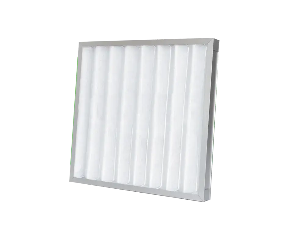
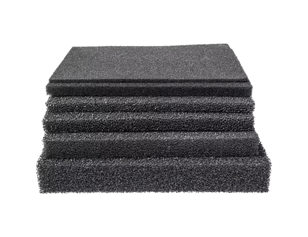


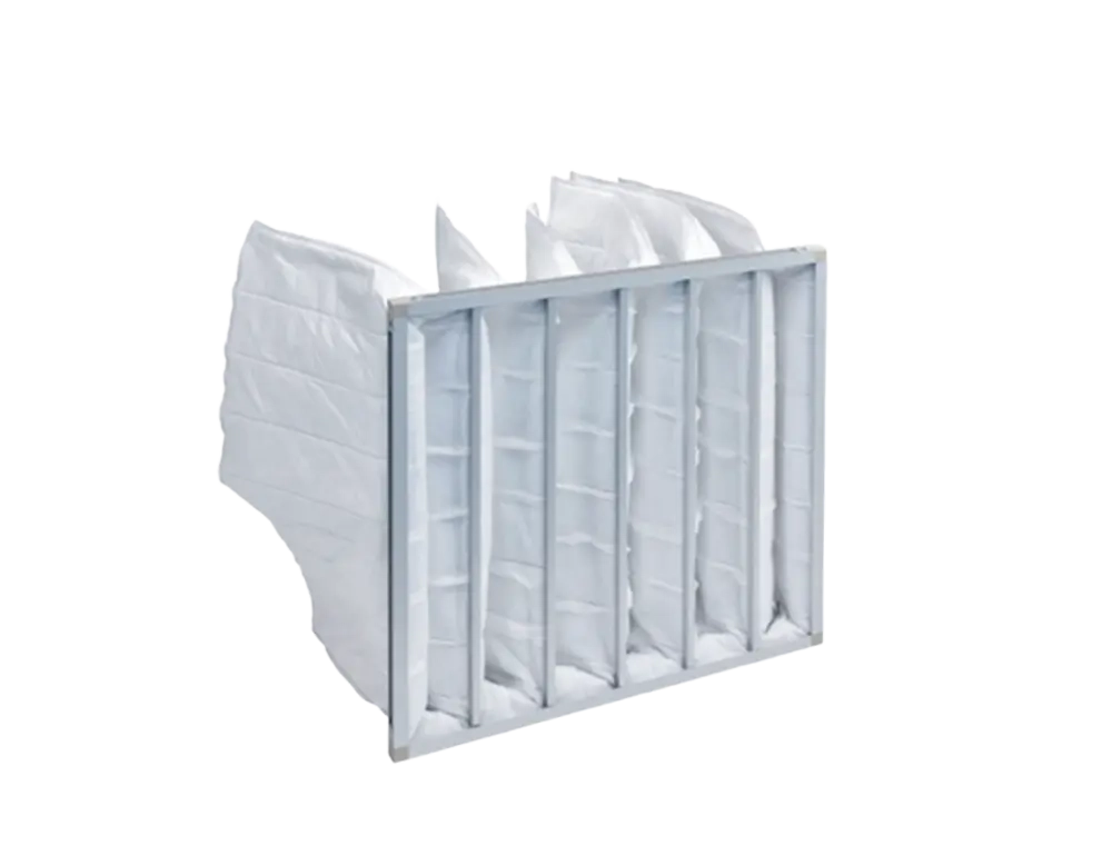
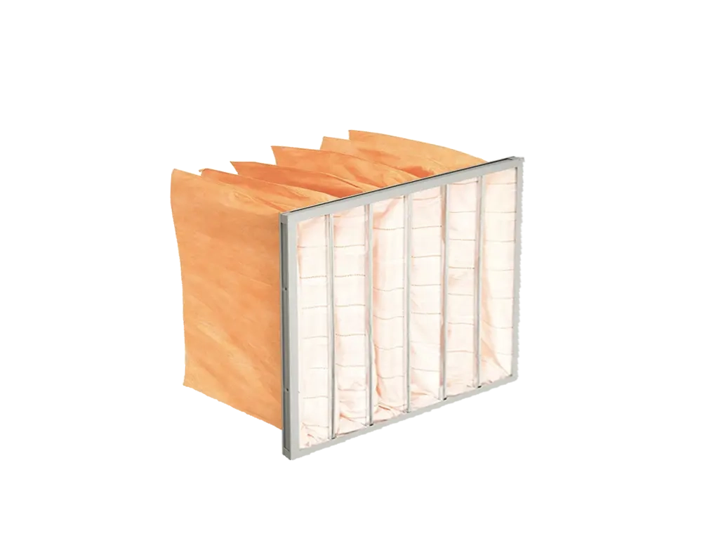
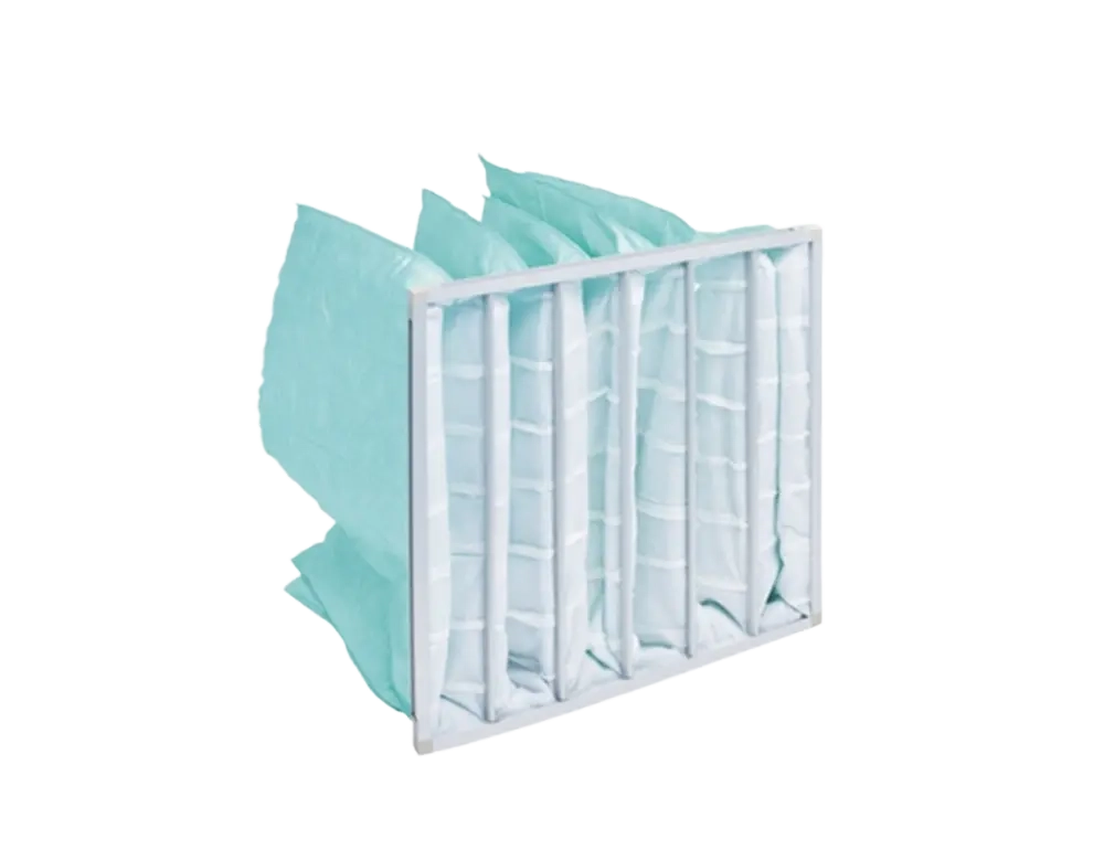

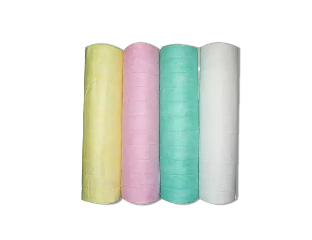
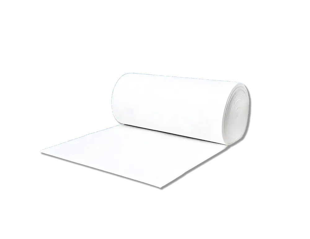
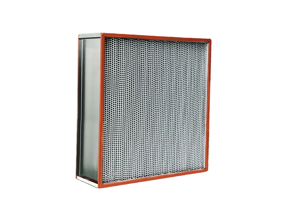
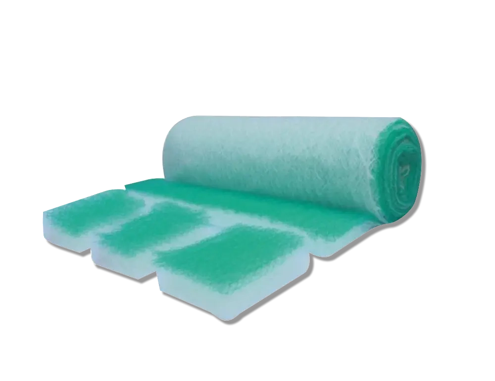
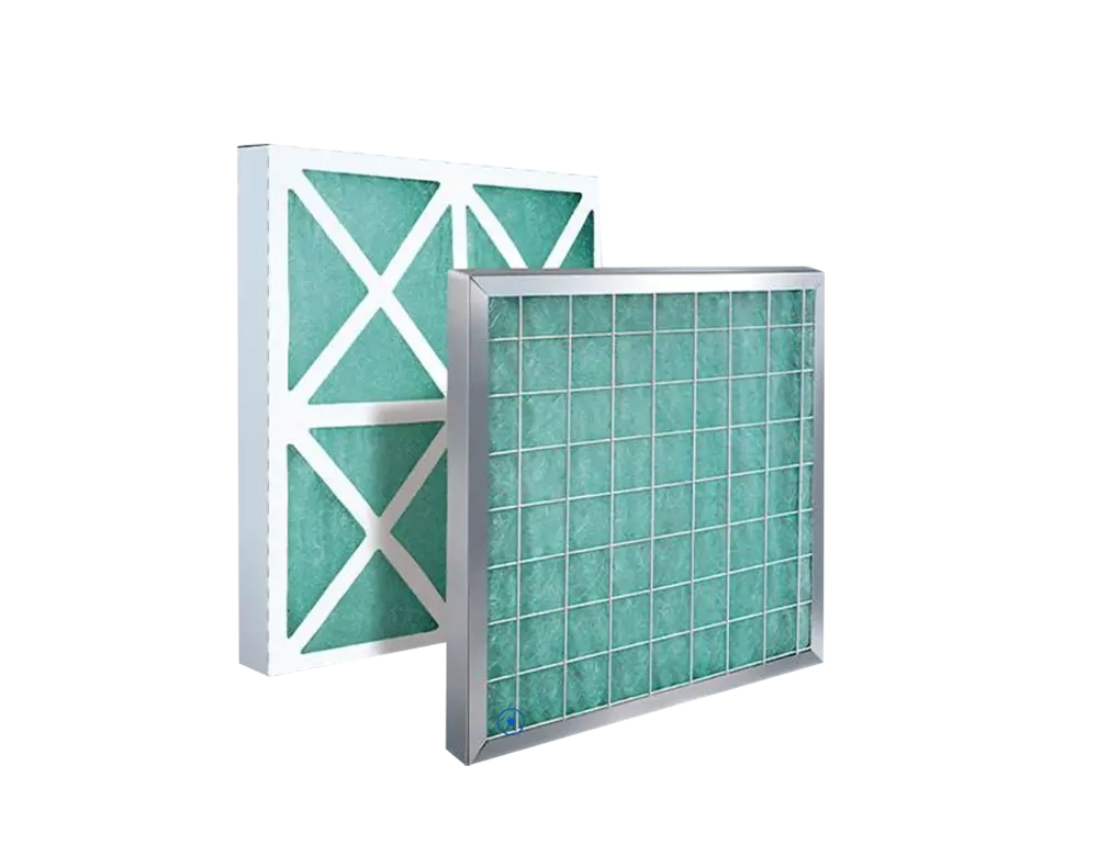
Pre-Filter (G1–G4)
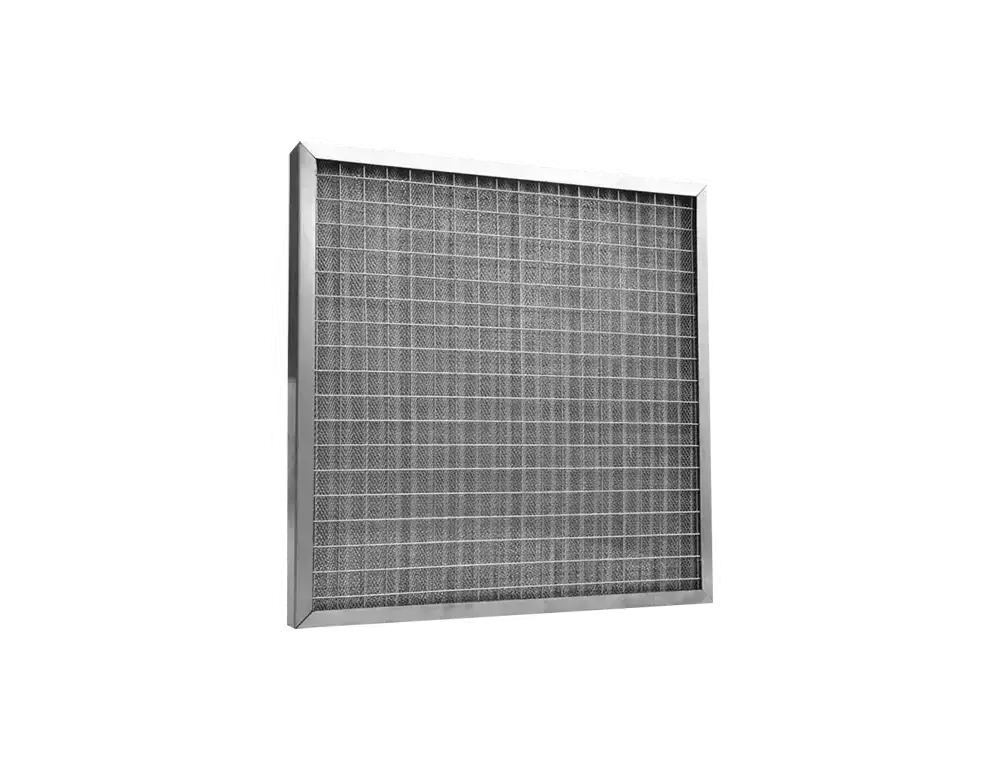
First-Stage Large-Particle Capture
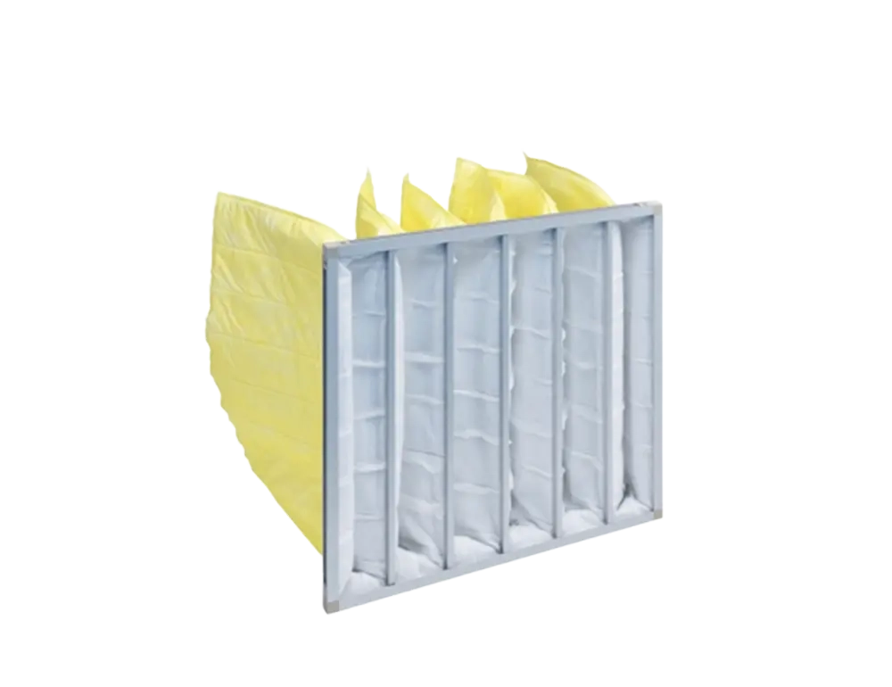
Medium-Efficiency Filter (F5–F9)
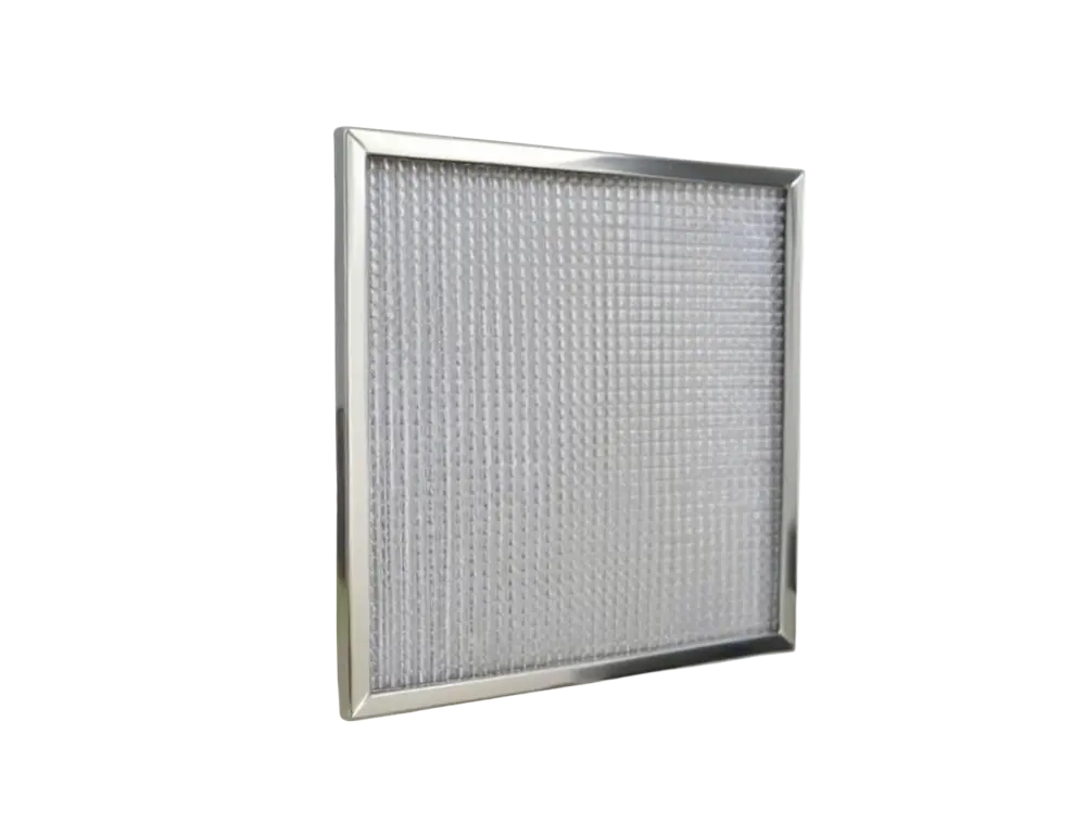
Precise PM2.5 Capture
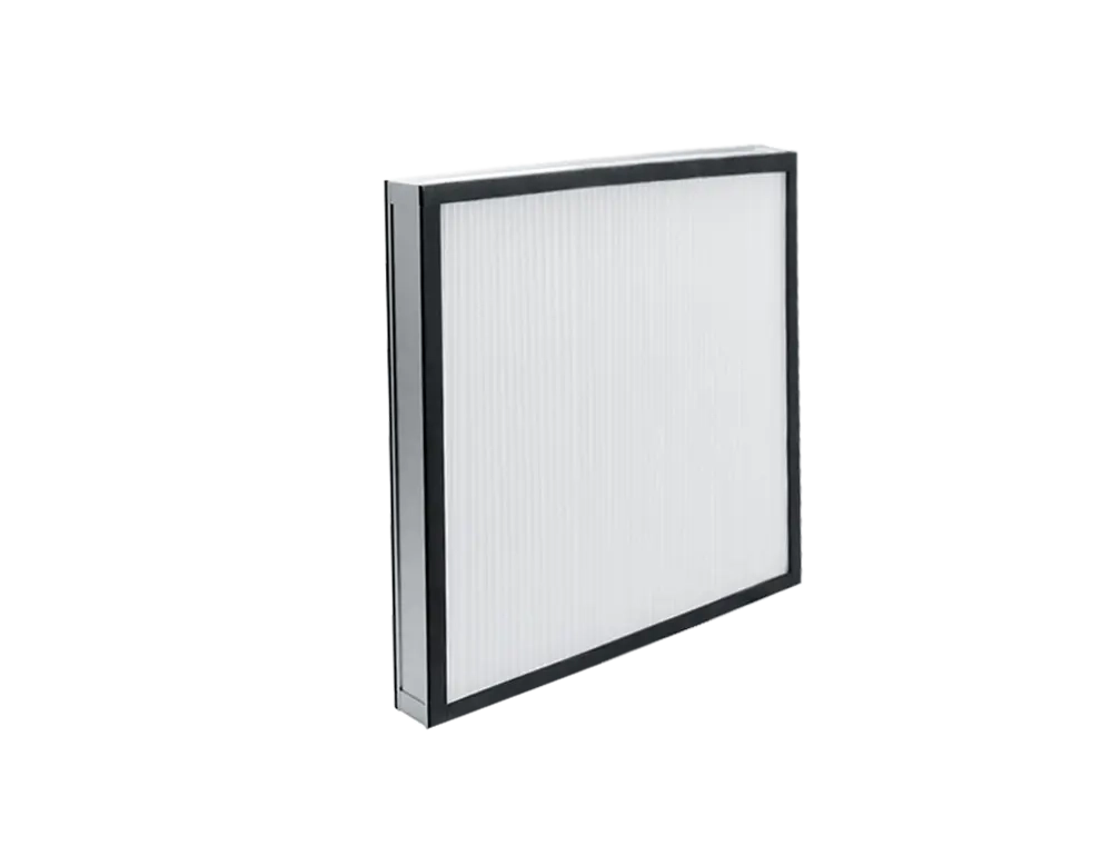
HEPA High-Efficiency Filter
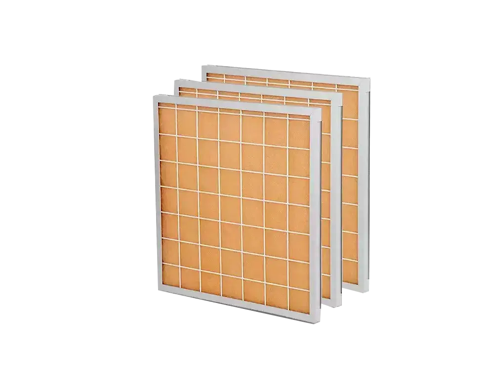
Sterile-Grade Purification
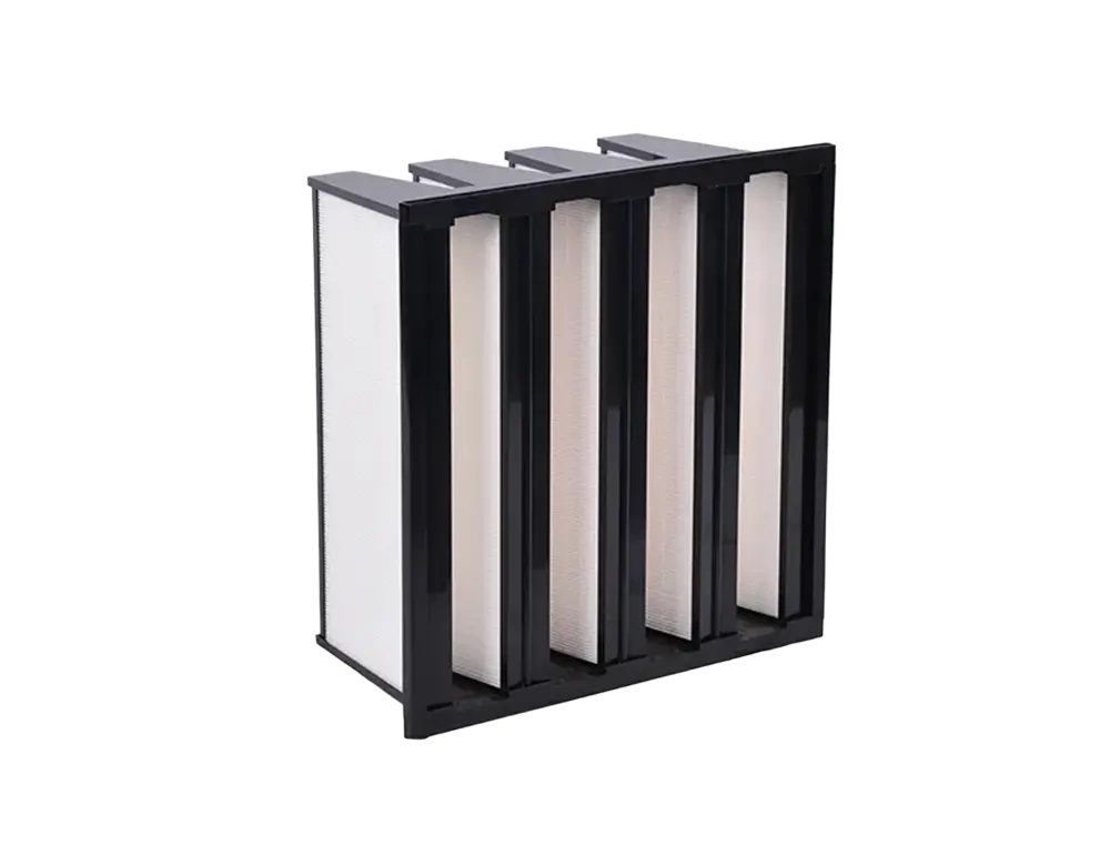
ULPA Ultra-High Efficiency Filter
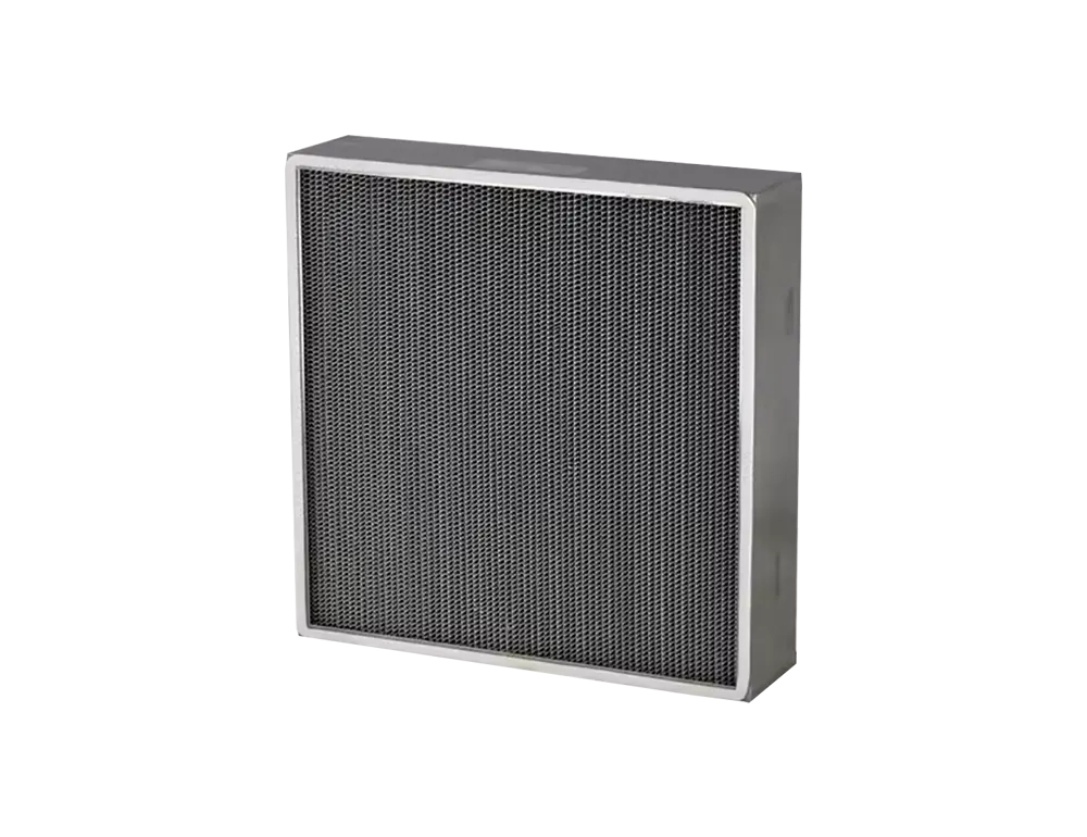
Sub-Micron Particle Capture
First-Stage Large-Particle Capture
The first line of defense, capturing particles ≥5 μm such as dust, hair, and fibers to protect downstream filters and extend overall system service life.
View Related Products →Precise PM2.5 Capture
Captures fine particles of 1–5 μm including PM2.5, pollen, and mold spores, significantly improving indoor air quality for commercial HVAC and ventilation systems.
View Related Products →Sterile-Grade Purification
≥99.97% filtration efficiency for particles ≥0.3 μm, delivering sterile-grade clean air widely used in medical, pharmaceutical, and electronics manufacturing.
View Related Products →Sub-Micron Particle Capture
≥99.9995% efficiency for particles ≥0.12 μm, meeting the extreme cleanliness demands of semiconductor fabs, aerospace, and other ultra-precision applications.
View Related Products →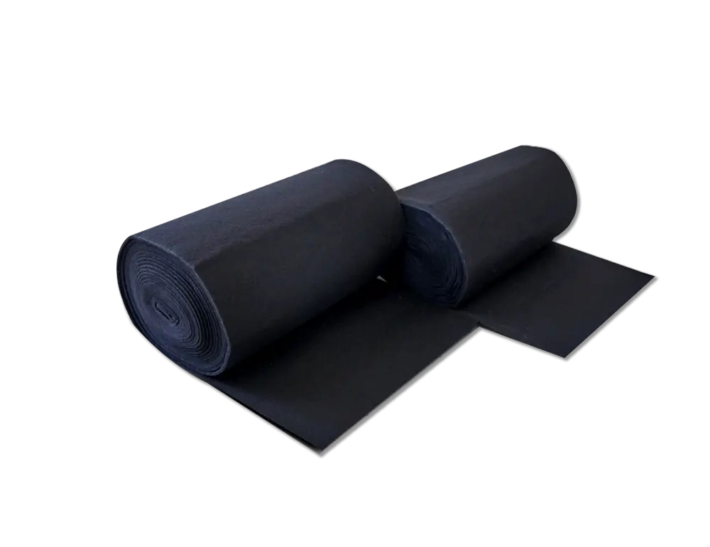
High-Temperature Resistant
Industrial-Grade Heat Tolerance
Washable & Reusable
Cut Costs, Reduce Waste
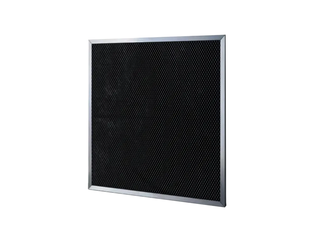
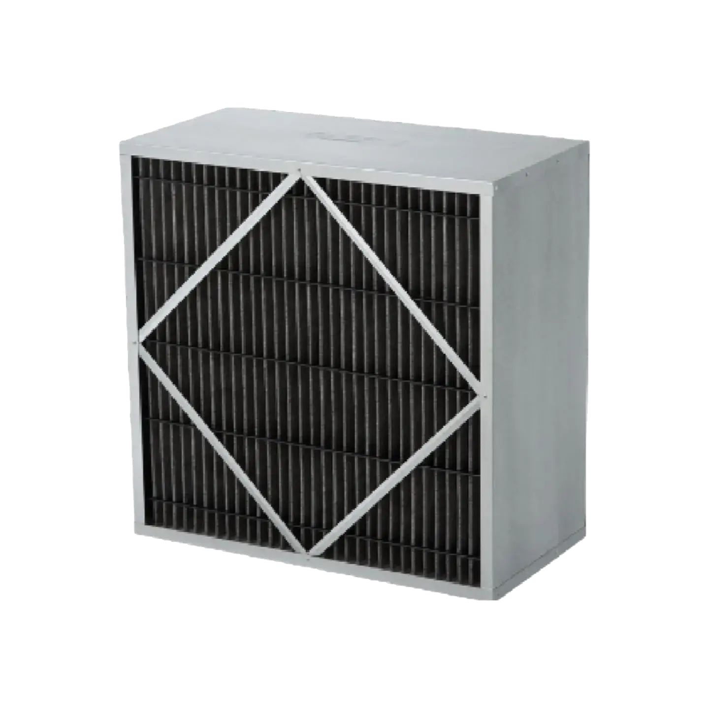
Activated Carbon
Odor & Harmful Gas Removal
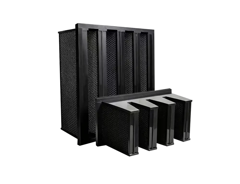
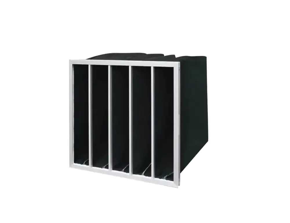
Bag Filter
High Dust-Holding, Long Life
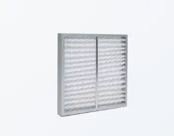
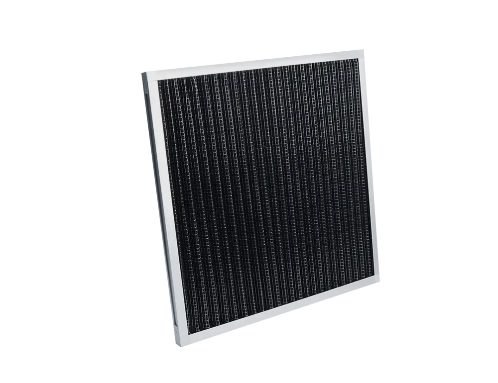
Panel / Pleated Filter
Compact Space-Saving Design
Low-Resistance Airflow
Energy-Saving Operation
Industrial-Grade Heat Tolerance
Built with specialized heat-resistant materials, operating stably up to 250°C for paint ovens, industrial dryers, and high-temperature process environments.
View Related Products →Cut Costs, Reduce Waste
Cleanable by water washing or air blowing, reusable multiple times to significantly reduce replacement frequency and O&M costs — an economical, eco-friendly choice.
View Related Products →Odor & Harmful Gas Removal
Leverages activated carbon's high adsorption capacity to eliminate odors, VOCs, and formaldehyde, ideal for newly renovated spaces and industrial exhaust treatment.
View Related Products →High Dust-Holding, Long Life
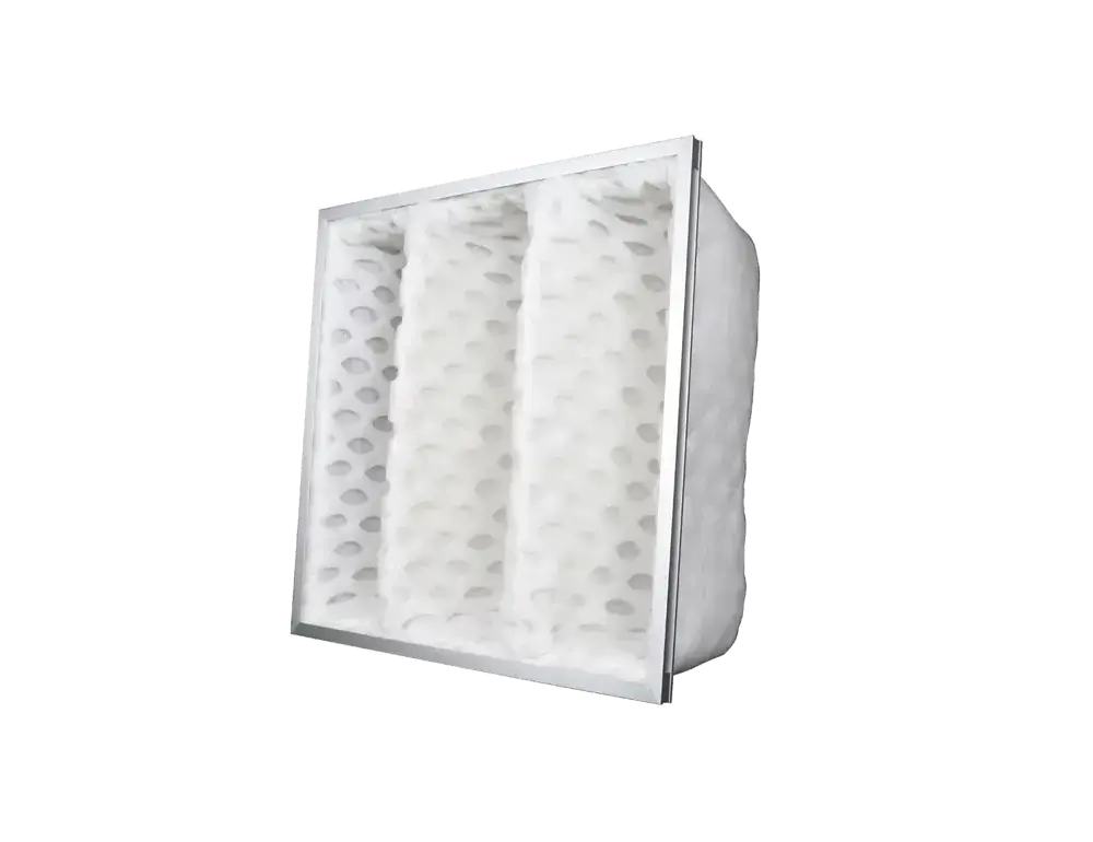
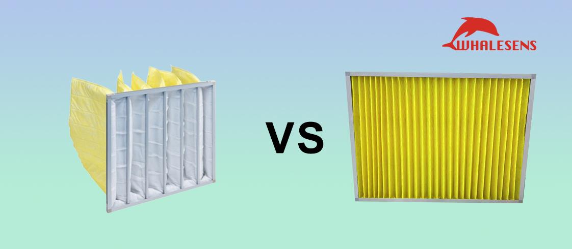
Bag-style construction delivers a larger filtration area, high dust-holding capacity, and extended service life — ideal for high-dust environments with reduced replacement frequency.
View Related Products →Compact Space-Saving Design
Compact form factor for easy installation and replacement; pleated structure maximizes filtration area within a small footprint for higher efficiency.
View Related Products →Energy-Saving Operation
Low-resistance design minimizes pressure drop while maintaining filtration performance, reducing fan energy consumption for cost-effective, eco-friendly operation.
View Related Products →


















 English(Global)
 简体中文
简体中文 Language




HEPA Filter Leak Test: Methods, Limits and Field Steps
An on-site HEPA filter leak test answers a narrow but decisive question: is the filter still sealed once it sits inside the system? A filter can pass every factory efficiency test and still fail in a ceiling void. Media, frame, sealant, gasket and mounting frame meet along seams, and any seam that is not properly compressed lets dirty air slip around the media instead of through it. That bypass air is never filtered, so particle counts, room pressure and recovery time all drift out of specification. What the leak test does is find each bypass path, mark its location, fix it and leave behind a record that can be traced.
Factory testing and on-site testing are two different jobs. On a standard test rig the numbers describe the media and the finished unit under controlled, repeatable conditions. On site the variables are a gasket that may or may not be compressed, gel that may or may not have reached the knife edge, a frame that may have warped, and media damaged during handling. That is why the standards treat the installed-system leak test as its own method: GB 50591-2010 Annex D covers the on-site scanning leak test, ISO 14644-3:2019 clause B.7 covers leak testing of the installed filter system, and IEST-RP-CC034 adds more detailed operating guidance. The two reports answer different questions, and a factory certificate cannot replace a leak test.
Acceptance logic differs from an efficiency rating as well. Efficiency describes an average across the whole filter, while the leak test looks at the local maximum: a single point above the limit fails the filter even when the remaining 99% of the face is perfect. Once that asymmetry is clear, every operating detail below makes sense. Buyers still comparing filter formats before they reach this stage will find the industrial and commercial HEPA filter guide a useful starting point.
How a leak test makes a bypass visible
The principle behind every leak test is simple. Generate a stable cloud of aerosol upstream so that all of the supply air carries it into the filter. Where the seal is intact, only a small and fairly even fraction of the aerosol passes through the media, and the downstream face reads uniformly low. Where a bypass exists, the downstream concentration over that small patch is distinctly higher than its surroundings. The instrument converts that difference into a penetration figure.
Upstream concentration is the reference for the whole leak test. Too low and small leaks disappear into instrument noise; too high and the filter is fed until it loads, which turns a quality check into contamination. GB 50591-2010 gives a range of 20 to 80 µg/L: below 20 µg/L sensitivity drops, while above 80 µg/L a long scan will foul the filter. A photometer normally covers 0.001 to 100 µg/L. On a log-scale instrument, the upstream concentration should exceed the smallest scale division by a factor of 10^4. Every leak test reading depends on this reference point.
The filter under test must be running between 80% and 120% of design air velocity. That sounds self-evident and is the step most often skipped. Run the leak test before airflow is balanced and the whole downstream reading is distorted, so the result can neither prove compliance nor locate a fault. Where several filters share one supply face, expose one unit at a time during the leak test when the construction allows, so that neighbouring filters do not interfere with each other.
Photometer, particle counter and smoke screening
Three techniques are used for a leak test in the field. Which one applies depends on filter grade, how strict the acceptance limit is and the conditions on site — not on which instrument costs more.
| Dimension | Photometer method | Particle counter method |
|---|---|---|
| What is measured | Aerosol mass concentration difference | Individual particle counts |
| Filter range covered | Maximum penetration 0.001% and above | Down to 0.0000005% penetration |
| Acceptance form | Local penetration 0.01% | Judged by the non-zero count principle |
| Typical application | H13/H14 terminals and mounting frames | U15–U17 and similar high-sensitivity work |
| Main trade-off | Limited resolution, depends on upstream calibration | Small probe, substantially longer scan time |
The difference comes down to what is being measured. A photometer reads total aerosol mass concentration; it responds quickly and is easy for a technician to operate, which makes it the practical tool for large-area scanning during a leak test. A particle counter counts individual particles, so it reaches far higher sensitivity and covers U15 to U17 filters, but its probe aperture is small and scanning one 600×600 filter takes noticeably longer. Smoke generation is qualitative only: it indicates roughly where a leak sits and is useful for quick troubleshooting, but it cannot serve as an acceptance criterion.
Aerosol selection also shapes the outcome of a leak test. Common liquid aerosols are DEHS, DES, DOS, DOP, PAO (polyalphaolefin), mineral oil and paraffin oil; solid options are PSL (polystyrene latex spheres) and ambient dust. DOP has largely been replaced by PAO on safety grounds in many settings. The photometer method calls for a polydisperse aerosol with a mass median diameter of 0.5 to 0.7 µm and a geometric standard deviation near 1.7, usually generated with Laskin nozzles. Keep the liquid level in the generator above 2.5 cm, because below that the generation rate and the particle size distribution drift and the trend on the display is no longer trustworthy.
Running a leak test step by step
Breaking a leak test into stages shows that most failures happen during preparation rather than during the scan itself.
Scan speed is the part of a leak test that deserves its own note. ISO 14644-3:2019 binds upstream concentration and scan speed together: with plenty of concentration in reserve the probe can move faster, and when concentration cannot be raised the scan has to slow down. The 5 cm/s figure often quoted across the industry is a conservative value, and the standard permits closer to 8 cm/s when concentration is higher. What has to be avoided is fast scanning on a weak aerosol, because small leaks pass under the probe and the leak test report shows nothing.
Where the 0.01% leak test limit comes from
GB 50591-2010 Annex D sets 0.01% as the leak test acceptance limit for the photometer method: hold the sampling probe static at one point on the downstream face, and any reading above 0.01% marks that point as a leak. The value does not mean the filter has failed its efficiency rating; it means one local spot has penetration that should not exist. It is the number most often quoted in a leak test report. The corrective action is different in each case — a failed efficiency rating calls for a replacement filter, while a local leak may need nothing more than the seal compressed again.
A particle counter follows different logic, and its leak test criteria are statistical. It applies the Poisson distribution and the non-zero detection principle: when no more than 3 counts appear in a sample volume, the reading can be treated as non-zero at 95% confidence and the point judged a leak. This is often misread as 'any particle detected means a leak'. Sampling volume and statistical significance matter, otherwise normal penetration is mistaken for a defect.
A leak test limit also depends on the contract and the industry. Sterile pharmaceutical plants generally work to EU GMP Annex 1 or the local GMP annexes, writing post-installation and periodic test results into the validation file, and most cite 0.01% directly. Where that limit has to be agreed with a customer before testing, the terminal HEPA filter selection guide sets out how the filter and the acceptance criteria are matched. Semiconductor and electronics fabs set their own limits according to process sensitivity and cleanliness class. Writing the limit into the contract and the validation protocol is worth more than arguing about a set of readings afterwards.
Field mistakes that undermine a leak test
Much of the reliability of a leak test rests on checks that look trivial.
Pre-test checklist for a HEPA filter leak test
- Has airflow been measured, and does the filter run at 80%–120% of design velocity?
- Was the upstream concentration calibrated in front of the filter under test instead of estimated at the main duct?
- Are probe distance, scan speed and pass overlap applied as one consistent set of parameters?
- Were the frame, sealing surfaces, gel seal and mounting frame joints scanned together with the media?
- Is the instrument within its calibration interval, and has the photometer been zeroed with the same aerosol?
- Does the record capture test point locations, readings, instrument serial number and operator?
Frames and sealing surfaces are the areas most often skipped and the most common source of bypass. A liquid tank HEPA filter seals when the knife edge presses into the gel so that the full perimeter closes; if the knife edge misses the channel during installation, or debris sits in the gel, the leak is right there and a leak test that scans only the media will never catch it. Gel-seal units are therefore the product most directly relevant to this topic, and the seal is the first place a leak test should look. When pressure drop reads abnormally low or cleanliness keeps fluctuating, suspect the seal before the media.
Scanning technique is another trap that produces a leak test report which looks clean but proves very little. A probe moved too fast, held too far from the face or run without overlap between passes leaves blind spots that still look acceptable on paper. Coverage cannot be reconstructed afterwards; it has to be executed to parameter on the day. When a suspect point appears, do not conclude immediately — confirm it with a static re-check, then mark it and schedule the repair.
When a leak test has to be repeated
Shorter intervals are not automatically better. A leak test introduces aerosol, and testing too often disturbs production while adding avoidable contamination load to the filter. The more practical approach is to read the results together with the pressure drop trend and environmental monitoring data: a slow rise in pressure drop means the media is loading normally, while a sudden fall or a cleanliness excursion usually points to seal failure — and that is a reason to schedule a leak test, not to order a replacement filter.
Read the other way round, leak test records are also the evidence for deciding whether a filter needs replacing. If two consecutive tests pass, repaired area is within the maker's allowance and pressure drop is still far from final resistance, there is no reason to swap filters on a fixed calendar. Semiconductor projects often keep a longer history of both pressure drop and test results, and the semiconductor fab air filtration guide shows how that data is used across a project. Done properly, the work pays off not in the pages of the report but in turning the question of whether a cleanroom is genuinely clean from an assumption into a traceable, reviewable data chain.
Need a custom air filtration solution?
Contact the Whalesens engineering team for product selection and OEM/ODM support.
Email whalesens@gmail.com
Related Products
These products cover the filtration stages discussed above; see each product page for full specifications.
 ProductLiquid Tank HEPA FilterKnife edge presses into the gel channel for a fully closed perimeter, lowering frame leakage risk once installedView product details →
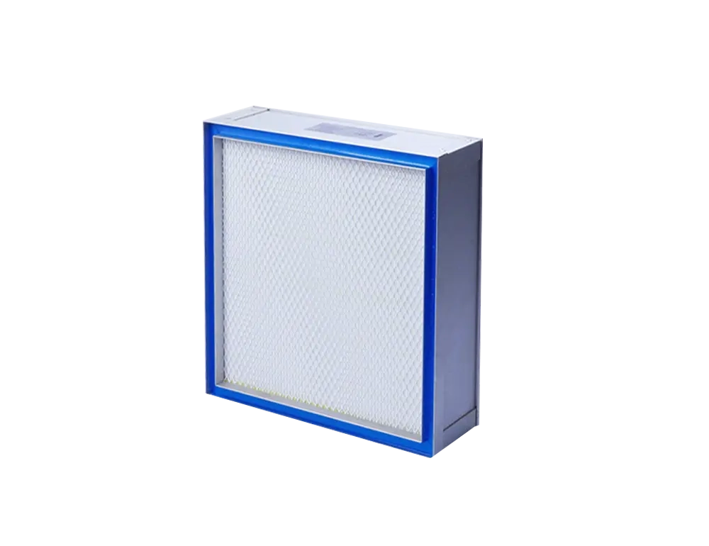
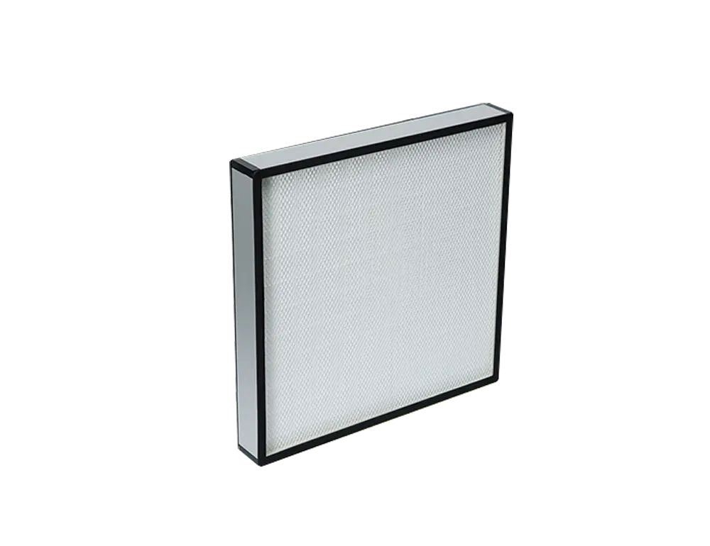
 ProductMini-Pleated HEPA FilterFills cleanroom terminal ceilings and is the usual subject of large-area scan testingView product details →
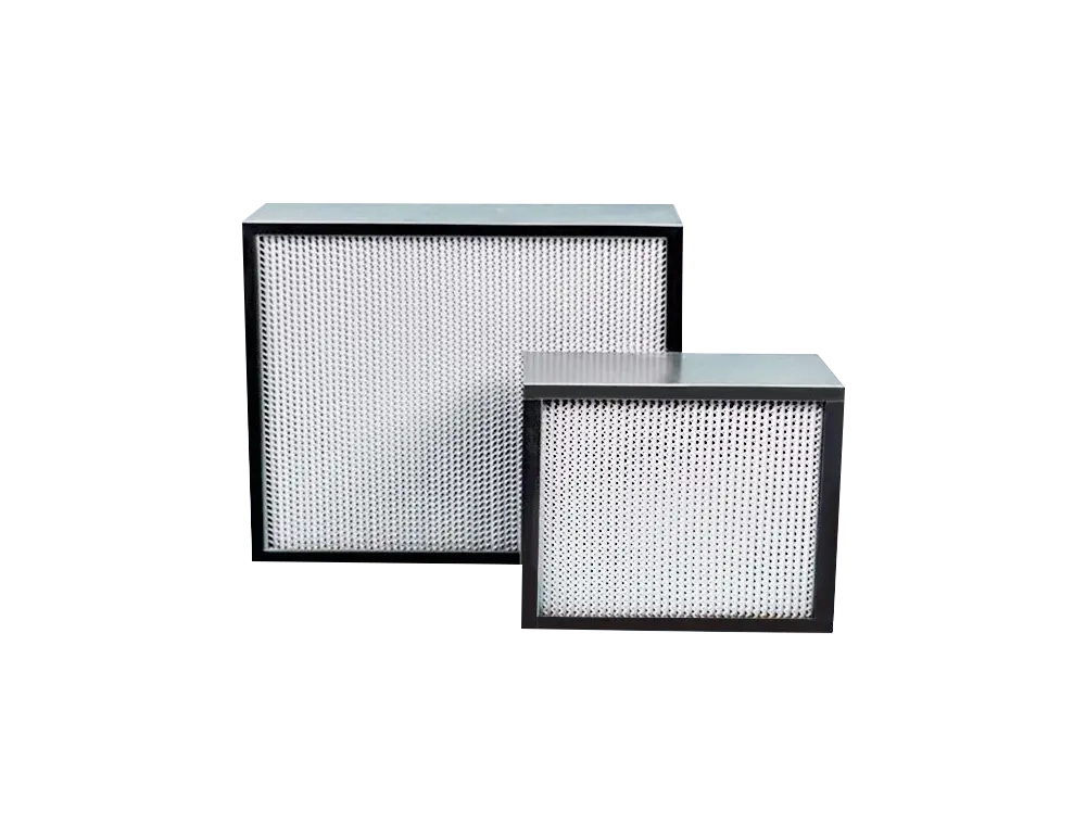 ProductDeep Pleated HEPA FilterBuilt for high airflow duty, where frame and gasket sealing faces are the test focusView product details →
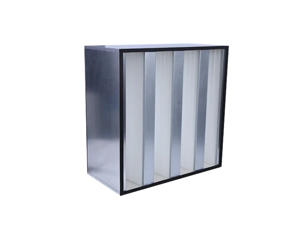 ProductV-Bank HEPA FilterLow-resistance, high-airflow terminals that are exposed one by one when installed side by sideView product details →
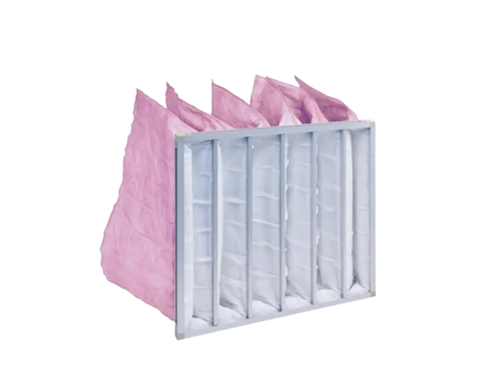 ProductF7 Medium Efficiency Bag FilterPre-filters the air ahead of the HEPA stage, cutting dust loading and retest frequency at the terminalView product details →
Frequently Asked Questions
The questions our engineering team receives most often on this topic.
How is a leak test different from an efficiency test?
An efficiency test measures average filtration efficiency on a standard rig and proves the product itself. A leak test scans the downstream face on site to find local bypass, so it proves the installation and the sealing. The acceptance limits, the instruments and the corrective actions are all different.
Does a leak test have to use PAO aerosol?
No. DEHS, DES, DOS, DOP, mineral oil and paraffin oil are all acceptable liquid aerosols, and PSL or ambient dust can be used as solid aerosol. DOP has been replaced by PAO in many settings for safety reasons; the choice should be agreed with the testing party and the customer in the protocol.
Does the 0.01% limit apply to every HEPA filter?
0.01% is the photometer penetration limit given in GB 50591-2010 Annex D and it suits H13/H14 filters that a photometer can cover. Higher grades are normally tested with a particle counter, where the acceptance limit follows the non-zero count principle and is agreed separately.
If a leak test fails, must the filter be replaced?
Not necessarily. Leakage at a frame, gasket or gel seal can often be solved by re-tightening or replacing the seal, and damaged media may be patched within the area and position the manufacturer allows. Only when the repair exceeds that allowance is a full filter replacement required.
How often should a HEPA filter leak test be performed?
It is mandatory after installation or replacement and after system modification. Periodic testing is usually annual, with shorter intervals in Grade A/B sterile areas; the final frequency should be set by risk assessment and the validation protocol.
